|
Uploaded: 7 years ago
Contributor: Guest
Category: Physics
Type: Solutions
Tags: current, circuit, magnetic, field, capacitor, voltage, induced, changing,
the, constant, conductor, energy, resistance, inductor, value, change, changes, across, produced, master, maximum, charge, inductance, opposes, circuits, induces,
inductive, varia
Rating:
N/A
|
Filename: Lecture - 20.ppt
(2.88 MB)
Credit Cost: 4
Views: 142
Last Download: N/A
|
Description
Physics for Bioscience (II)
Transcript
Chapters
Magnetic Field
Chapter 22
Sections 22.2 to 22.10
Chapter 23
All
Skip Chapter 24 (use notes)
Optics
Chapter 25
Chapter 26
Chapter 27 (reading only)
REVIEW
Recap
DC Circuits
Resistive Circuit
Capacitive Circuit
Why does a current lead voltage (physical reason)
Inductive Circuit
Why does a current lag voltage (physical reason)
RLC Circuit
Click to edit Master title style
Click to edit Master text styles
Second level
Third level
Fourth level
Fifth level
Click to edit Master text styles
Second level
Third level
Fourth level
Fifth level
Instructor
Franco Gaspari
PHY 1040U
(Physics for the biosciences)
Introduction to Electromagnetism and Optics
Lecture 20
March 30, 2007
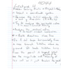
An induced e.m.f. is produced in the secondary loop by a changing magnetic field (or when the number of field lines changes, as in case 1).
The emf induced in a circuit is directly proportional to the time rate of change of the magnetic flux through the circuit.
Magnetic Flux
If the circuit is a coil of N turns
Suppose we have a uniform magnetic field through a loop of area A.
This means that we can induce an emf by
1. Changing the magnitude of B with time.
2. Changing A with time.
3. Changing the angle with time.
4. Any combination.
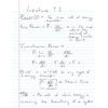
EXAMPLE 1
A coil is wrapped with 200 turns of wire on a square frame of 18 cm sides.
18 cm
N 200
is turned on perpendicularly to the plane of the coil.
A uniform
If the field changes linearly from 0 to 0.5 Wb/m2 in 0.8 s, find the emf while the field is changing.
Example 2
Instead of changing the magnetic field, let us see what happens when we move a conductor through a magnetic field.
Remember the Hall effect
As with the Hall effect, an electric field will be produced inside the bar until
Since E is constant, we have
A potential difference is maintained as long as the conductor moves through the field. If the motion is reversed, the polarity of V is reversed.
Consider the conductor now as part of a closed conducting path.
The conductor is sliding along two fixed parallel rails.
Assume the resistance of the conductor 0, i.e., all the resistance of the circuit is included in R.
Force pulling the bar
Assume a constant velocity.
As the conductor of length L moves through the magnetic field, it will experience a magnetic force (due to the induced current)
The force will act opposite the motion of the bar.
At constant velocity
This power is equal to the rate at which the energy is dissipated in the resistor I2R
The induced current will appear in such a direction that it opposes the change in flux that produced it.
_
Consider a loop of wire in a constant magnetic field. If we rotate the loop the flux through the cross sectional area will change.
By Faradays Law an Induced EMF will be generated.
The converse is also true if we run a current through the wire then a torque will be excerted on the loop making it turn.
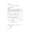
Generators and motors
(a) Schematic diagram of an AC generator. An emf is induced in a loop that rotates in a magnetic field. (b) The alternating emf induced in the loop plotted as a function of time.
Generators and motors
After the switch is closed, the current produces a magnetic flux through the area enclosed by the loop. As the current increases toward its equilibrium value, this magnetic flux changes in time and induces an emf in the loop.
A changing magnetic flux induces an emf.
A variable current induces a variable magnetic field, i.e. flux.
Then
L is a proportionality constant, called the inductance of the coil.
It depends on the geometry of the coil (similar to C and R).
also
If the resistance R is a measure of the opposition to current, the inductance L is a measure of the opposition to the change in current.
A series RL circuit. As the current increases toward its maximum value, an emf that opposes the increasing current is induced in the inductor.
Remember the inductance opposes the changes in the current
The solution to this differential equation gives
LC Circuits
Consider the LC and RC series circuits shown
Suppose that the circuits are formed at t 0 with the capacitor C charged to a value Q. Claim is that there is a qualitative difference in the time development of the currents produced in these two cases. Why
RC/LC Circuits
RC
current decays exponentially
-i
- - -
LC
current oscillates
- - -
At t 0, the capacitor in the LC circuit shown has a total charge Q0. At t t1, the capacitor is uncharged.
(a) Vab 0
(b) Vab 0
(c) Vab 0
Vab is the voltage across the inductor, but it is also the voltage across the capacitor
Since the charge on the capacitor is zero, the voltage across the capacitor is zero
What is the value of Vab, the voltage across the inductor at time t1
LC (ideal case) and LCR (real life) circuits
LC circuit summary In an LC circuit that has zero resistance and does not radiate electromagnetically (an idealization), the values of the charge on the capacitor and the current in the circuit vary in time according to the expressions
The energy in an LC circuit continuously transfers between energy stored in the capacitor and energy stored in the inductor. The total energy of the LC circuit at any time t is
Oscillations in an LC Circuit Practice problem
AC Sources
Amplitude of the emf
Phase
Phase constant if the current is not in phase with the emf.
AC stands for Alternating Current, which can refer to either voltage
or current that alternates in polarity or direction, respectively.
Resistive Circuit
Capacitive Circuit
Inductive Circuit
D V
D V
D V
D V
I 0
I,V
I
I
D j
Capacitive Reactance
D V
I
D j
Inductive Reactance
D V
I
Impedance
c
c
c
c
The instantaneous current in the circuit is
The denominator plays the role of the resistance and is called the impedance Z of the circuit
The maximum current is
The angle between the current and the voltage is
Open S1 and close S2.
The rate of energy transformation within the resistor R is
Ideal case with no resistor
Divide by I and solve the differential equation gives the angular frequency of oscillation
The current will be maximum when Z is minimum
Not a real life case
The other solution is to make (XL-XC) 0, i.e.
Resonance
x
|
|