Transcript
KINETICS OF PARTICLES & RIDGID BODIES
0-285752 m
2 m
2 m
E
20 kg
20 kg
20 kg
40 kg
B
C
D
A
x
y
00
2 m
2 m
2 m
E
20 kg
20 kg
20 kg
40 kg
B
C
D
A
x
y
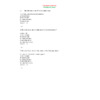
Three 20 kg packages rest on a belt which passes over a pulley and is attached to a 40 kg block. Knowing that the coefficient of friction between the belt and the horizontal surface and also between the belt and the packages is 0.50, determine the speed of package B as it falls off the belt at E.
Assumption: Packages do not slip on belt.
266700363220F
NP
196.2N
00F
NP
196.2N
Free-body diagram for a typical package.
Packages do not move belt Fy = 0: 196.2 – Np = 0 Np = 196.2 N
Friction: F = Np = 0.5(196.2) = 98.1 N
Principle of Work and Energy: U12 = T2 – T1
Belt not moving initially T1 = 0
T2 =
U12 =
Check on assumption of no slipping:
For 1 package: U12 = F(2), T1 = 0,
2 F = 39.24 F = 19.62 N
But Fmax = 98.1 > F Packages do not slip.
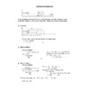
0000As the bracket ABC is slowly rotated, the 6 kg block starts to slide toward the spring when = 15. The maximum deflection of the spring is observed to be 50 mm. Determine the values of the coefficients of static and kinetic friction.
Free-body diagram
-114306858058.86N
= 15o
F
NP
y
x
= 15o
0058.86N
= 15o
F
NP
y
x
= 15o
Static Case
Fx = 0: 58.86 sin 15 – F = 0 (i)
Fy = 0: Np – 58.86 cos 15 = 0 (ii)
Friction: F = sNp = s(58.86 cos 15)
From (i) 58.86 sin 15 = s (58.86 cos 15)
Dynamic Case
Principle of Work and Energy: U12 = T2 - T1
T1 = 0 (block starts from rest), T2 = 0 (at maximum deflection of spring, block is again at rest)
; Fmin = k1 = 0 (since spring is undeformed initially i.e. x1 = 0)
58.86(0.3)(sin 15 - k cos 15) – 2 = 0
1. A 1500 kg automobile travels 200 m while being accelerated at a uniform rate from 50 to 75 km/h. During the entire motion, the automobile is traveling on a horizontal road, and the rolling resistance is equal to 2 percent of the weight of the automobile. Determine (a) the maximum power required, (b) the power required to maintain a constant speed of 75 km/h.
731520701040002. A slender rod AB of negligible mass is attached to blocks A and B, each of mass m. The constant of the spring is k and the spring is undeformed when AB is horizontal. Determine the potential energy of the system with respect to (a) the spring, (b) gravity. (Place datum at B.)
3. The spring AB is of constant 1.2 kN/m and is attached to the 2 kg collar A which moves freely along the horizontal rod. The unstretched length of the spring is 250 mm. If the collar is released from rest in the position shown, determine the maximum velocity attained by the collar.
548640000
04762500The 5 kg bar shown in the figure has a center of mass at G. If it is given an initial clockwise angular velocity of 1 = 10 rad/s when = 90, compute the spring constant k so that it stops when = 0. What are the horizontal and vertical components of reaction at the pin A when = 0? The spring deforms 0.1 m when = 0.
Forces which do work are the weight and the spring force
Principle of work and energy can be used to determine the spring constant k
9144013525500Kinetic energies:
(bar stops when = 0)
Work done
Principle of Work and Energy:
30 + 14.715 – 0.005 k = 0
Note: T1 can be calculated alternatively as T1=
T1 =
Ay and Ax do no work must be obtained from the equations of motion
9144019431000301752030099000 Free-body diagram Kinetic diagram
47548809144000
5067300863600048844208636000
479298023304500
See kinematics below
Fs = kx = 8943(0.1) = 894.3 N
From 49.05(0.3) – 894.3(0.6) = 0.6 = -869.8 rad/s2
From Ay + 894.3 – 49.05 = -(0.3)(5)(-869.8)
209550013970000136207513970000
Kinematics: (A is fixed)
91440000The 100 kg wheel shown in the figure has a radius of gyration of kG = 0.25 m about its center of mass G. If it is subjected to a clockwise couple of 20 Nm as it rolls on its inner hub without slipping, determine the wheel’s angular velocity after the 20 kg block is released from rest and has fallen 0.4 m. The spring has a stiffness of k = 60 N/m and is initially unstretched when the block is released.
Angular velocity is required Principle of work and energy is the most “economical” analytic tool to use.
It is easier to analyze the system as a whole than to consider the components separately
14986029337000Position
27432032067500Position
Kinetic Energies:
18288024765000Work done
Nw and R do not work since they do not move along their lines of action
Fr does no work since wheel does not slip as it rolls
Wheel does not slip wheel moves through as block moves a distance s such that
spring stretches = rD/Ic = (0.4)(0.571) = 0.228 m
Principle of Work and Energy:
20955011366500
4526280-4572000The uniform rods AB and BC are of mass 3kg and 8 kg, respectively, and collar C has mass of 4 kg. If the system is released from rest in the position shown, determine the velocity of point B after rod AB has rotated through 90o.
Only gravity forces, which are conservative, are present
Energy is conservative
4572073025
0.18m
0.18m
WAB
WBC
WC
C
A
00
0.18m
0.18m
WAB
WBC
WC
C
A
1224915162560Potential Energy Datum
00Potential Energy Datum
37299908255
(WBC)2
(VG1AB)2
0.075m
0.195m
G2
G1
B
A
C
0.195m
0.075m
(VG2Bc)2
VB
00
(WBC)2
(VG1AB)2
0.075m
0.195m
G2
G1
B
A
C
0.195m
0.075m
(VG2Bc)2
VB
205740038735j
k
00j
k
270700553975i
00i
MAB = 3 Kg, MBC = 8 Kg, MC = 4 Kg
Kinematics: Rod AB:
Rod BC: Instantaneous Centre is at C VB = 0.39
Kinetic Energies
1841500-48323500
T1 =0; T2 =
Potential Energies
V1= WBC (-0.180) + WC (-0.360) + WAB (0) = 9.81
V1=-28.253 J
V2 =WAB (-0.075) + WBC
= 9.81 [3(-0.075) + 8 (-0.345) + 4(-0.54)]
V2 = -50.472 J
Conservation of Energy: T1 + V1 = T2 + V2
0 +(-28.253) = + (-50.472)
4114801905
00
06731000
The 10-kg rod AB shown is confine so that its ends move in the horizontal and vertical slots. The spring has a stiffness of k = 800 N/m and is unstretched when = 0o. Determine the speed of the slider block at B when = 0o, if AB is released from rest when = 30o. Neglect the mass of the slider blocks.
-16002021971000333756025273000Position1 Position 2
Only conservative forces (gravity and spring force) are present Energy is conserved
Rod is released from rest in Position 1
(VG)1 = W1 = 0 T = 0
V1= Vg1 + Ve1 = 98.1Y1 + ½ k x12
V1 = -98.1 (0.2sin30°) + ½ (800) (0.4sin30°)2
=-9,81 + 16 = 6.19 J
T2= ½
29718005270500
T2=
T2= 5(0.2)2
V2 =
Conservation of Energy: T1 + V1 =T1 + V2
13716085090W =
00W =
137160130810
00


")

")


")


")


